Ok, so I’m one of those people who are glad when I finally get something working but it gnaws at me if I don’t fully understand the details of why it works. Such is the case with this post. The background is that I’m working on a little project for a friend and wanted to minimize the hardware as opposed to simplifying the software. That being the case, I decided to forego my now world famous 3-wire, 8-bit implementation of the 1602 LCD interface and go with a more standard 4-bit parallel interface. I figured it would be easy because I had already made a working 8-bit parallel interface and because there were tons of examples on the web of the simple changes needed for 4-bit mode. Silly me. The hardware was simple but the problem came when I tried to make the “simple” changes to the software. In the interest of building dramatic tension I will save those sad details for the software section.
Hardware
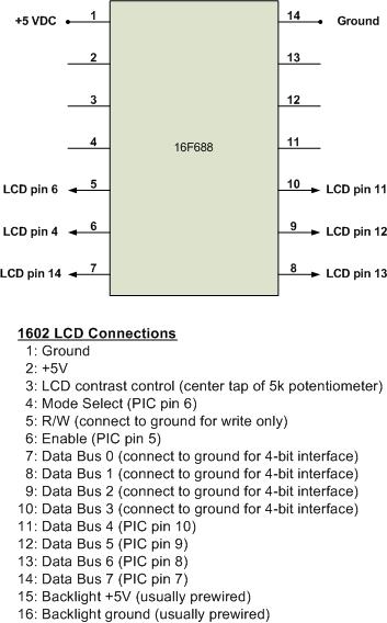
As seen in the schematic, the hardware is pretty simple. The wiring is exactly the same as for an 8-bit parallel interface except that LCD Data Bus lines 0 through 3 are hard wired to ground. When the LCD initially comes up it is in the 8-bit mode but the first set of commands we will send all have a lower nibble equal to zero. Once we put the LCD into 4-bit mode, we will send each byte of data as two consecutive nibbles using just the upper four Data Bus lines. Sometimes the backlight connections are pre-wired and sometimes they aren’t. It doesn’t hurt to always wire them. I have also found that some LCD modules only have 14 pins (the backlight pins are not provided).
Software
The software link is listed below. While it is targeted for the 16F688, it is easily ported to other versions of the PIC. You will need to change the line that identifies the PIC version (LIST=) and the INCLUDE file but those are intuitive changes. The __CONFIG line may also need tweaking just because one or two of the labels used are spelled differently in some of the INCLUDE files.
As mentioned in the hardware section, the LCD starts out in the 8-bit mode and must be commanded to the 4-bit mode. If you look at the LCD initialization section you will see that the first four commands are sent while the LCD is in 8-bit mode. Because the LCD will see the grounds on the lower four data lines, we send only the upper nibble of the data. For example, in the 8-bit interface version we would send hex bytes 30, 30, 30 to tell the LCD that we want to reinitialize it. In the 4-bit version we send hex nibbles 3, 3, 3 but the LCD sees 30, 30, 30. The fourth nibble we send is 2 which the LCD sees as 20. This tells it to switch to the 4-bit mode. After that point we will need to send each data byte as a pair of nibbles and the LCD will stitch them together internally before processing them. The rest of the initialization commands have the same values as in the 8-bit version except that we send 28 instead of 38 for the function set command. That’s because “2” means 4-bit mode while “3” means 8-bit mode.
Because we need to send each byte as consecutive nibbles we add a few lines of code to the “Write_LCD” routine. The LCD expects the upper nibble first so we do a nibble swap to put the upper nibble in the lower four bits and then mask off the upper four bits. When we send the lower nibble we don’t do the swap and just mask off the upper four bits. Pretty simple changes but for the longest time I couldn’t get it to properly display my data messages. I figured something must be wrong with the “Write_LCD” routine but the confusing thing was that the routine worked just fine when sending the initialization commands. It only messed up when I tried to switch the LCD to data entry mode. What I finally settled on as a solution was to add a 50us delay just prior to the enable pulse that tells the LCD to capture the first nibble. Once I got it working I tried less delay (it worked down to about 25us). I also tried putting the delay just before the enable for the second nibble but that didn’t work. Interestingly, putting the delay inside of the first enable pulse did work. I scoured the spec for the Hitachi LCD controller chip but found nothing that explained the need for the extra delay – only while in data mode, and only while the first nibble of each byte is being processed. It simply said that you should check the “Busy Flag” after each piece of data sent but that requires the complexity of switching the LCD to read mode. It turns out that the millions of examples on the web were of no help either and many of them left me wondering if they really worked as written. I do have several different versions of the LCD so it doesn’t seem to be an anomaly in just one of them. It’s still driving me a little crazy not knowing “why”.
In the interest of completeness, I should mention that the first three “Special Function Set” commands (the 3, 3, 3) are probably not necessary. If the LCD powers up properly then the spec says you can go directly to sending the command for 4-bit mode. It doesn’t hurt to leave those first set of commands in there and they may help if the LCD does not power up correctly on occasion. That’s why I put them there. That’s it for this post. Check out my other electronics projects at http://www.boomerrules.wordpress.com
